
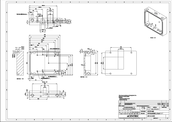
The current process
When a new part arrives for inspection, the quality engineer opens the technical drawing (usually a PDF) and manually reads every dimension, tolerance, and surface finish callout. They type each value into a spreadsheet or inspection report template, creating a checklist of what needs to be measured.
This process can take anywhere from 20 minutes for a simple part to several hours for a complex one with dozens of dimensions. And it's repeated for every new part number. The work is skilled: you need to understand GD&T and know what to look for, but the actual data entry is purely manual.
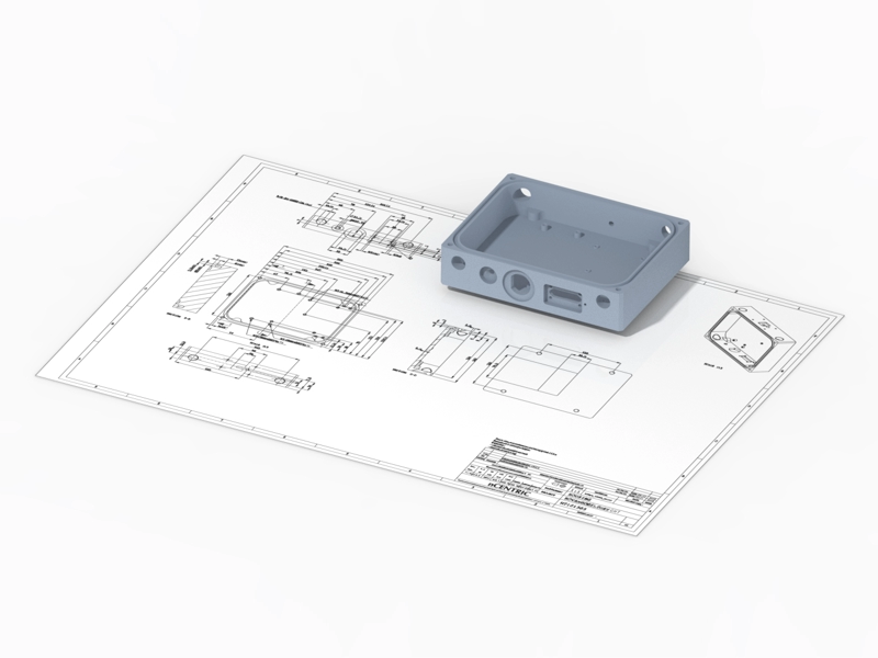
Where errors creep in
The risk isn't that the engineer doesn't know what they're doing. The risk is transcription errors. A tolerance of ±0.05 typed as ±0.5. A dimension missed because it was on a detail view on page 3. A reference datum overlooked. These errors propagate into the inspection process and can result in parts being accepted or rejected based on wrong criteria.
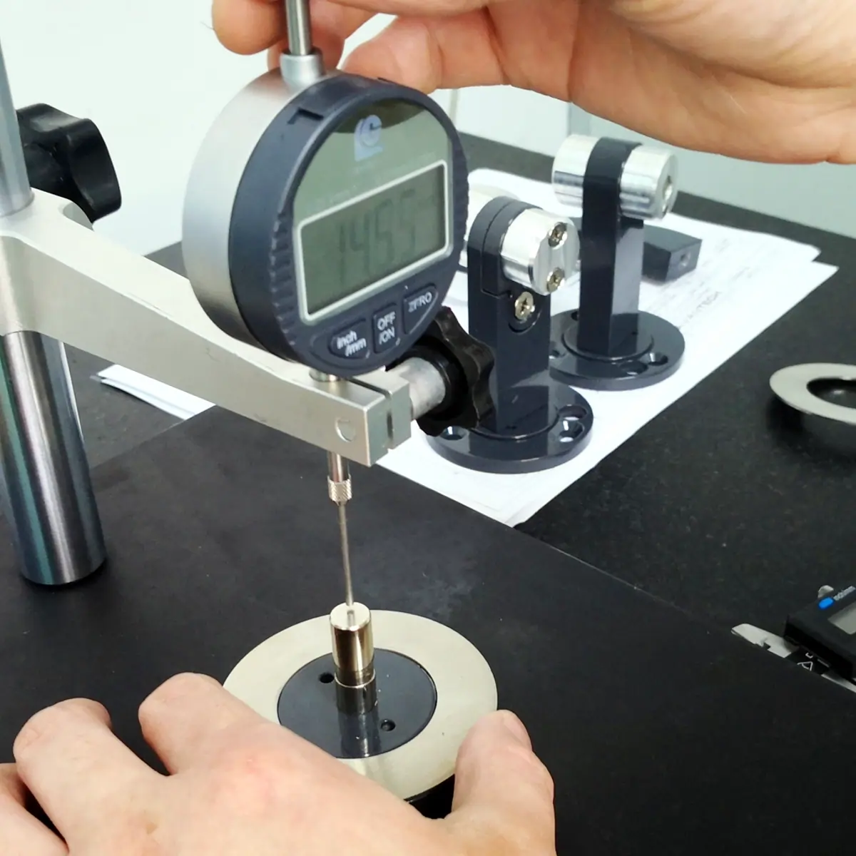
What automation looks like
Automated dimension extraction reads the drawing file (PDF or 2D STEP), identifies the dimensioned features, and outputs a structured list of dimensions with their tolerances. The quality engineer reviews and edits the list (adding context, removing irrelevant dimensions, adjusting priorities), then exports it as a measuring report template.
The engineer's expertise is still essential for review and judgment. But the tedious data entry is eliminated. A process that took an hour now takes minutes.
What a good measuring report template contains
Whether you build it manually or extract it automatically, a usable inspection template has the same structure. Each line item should carry:
- Balloon number and feature reference. So anyone reading the report can trace the measurement back to the exact callout on the drawing without opening it.
- Nominal dimension and tolerance. Both the target value and the acceptable range, exactly as the drawing states them. Asymmetric tolerances (for example +0.05/-0.00) must be preserved, not averaged.
- Measured value and the tool used. A caliper reading and a CMM reading are not equivalent evidence. Recording the instrument makes the report defensible in a customer or audit review.
- Pass/fail result and inspector sign-off. The verdict and who is accountable for it, with a date.
A common mistake is treating the template as a fixed form reused across parts. It works better as a per-part document generated from the drawing itself, so it only contains the features that exist on that part. Generic templates force inspectors to skip irrelevant rows, which trains them to skip rows in general.
First article inspection vs in-process checks
The same template serves two different moments. For a first article inspection (FAI), every dimension on the drawing is measured and recorded once, to prove the process can produce the part to spec. For in-process or final inspection, the template is trimmed to critical features and measured per lot or per serial. Building both from one template keeps them consistent and halves the setup work.
Asytra Measure
This is exactly what Asytra Measure is being built to do. Upload a PDF or 2D STEP file, review the extracted dimensions, edit as needed, and export a structured measuring report template. Currently in development. Register for early access to be notified at launch.